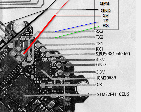
OK looking to add a couple of bits to my new TinyApe and there’s a 4.5V pad. Weird. never seen that before under the SBUS on the right… Now the 5V pads shown are taken and I’d rather not solder there if I have to.
There is no continuity to the “4.5V” pad to the other 5V pads on the board. I used a multi meter to measure the voltages, and we’ve got 3.28 on the 3.3, 5.08V on the 5V, and 4.8V on the 5V… Strangely it’s marked as 5V on the board (though I guess a “4.” could be hidden under the chip that’s next to it. Is 4.8V enough to run what I want? Runcam Thumb and a GPS.
Other option is to use one of my new “BECS” I bought last week, though this frame… for a buzzer, and a GPS to fit will be a struggle to add a BEC too… Ergh… I do have an idea which would fit all three…
yeah did think about the current… Those BECs be OK with thumb and GPS. Assume GPS aint much but believe the RC thumb can draw a bit. Just solder to the VBAT in yeah?
Sounds like a Matek board, 4v5 is usually a 5v supply derived from the USB. It is a bit less than 5v because it passes through a diode to give it reverse protection. I use it to power my RX and GPS so I can set up with just the USB plugged in. Although it is marked as 4.5v the diode only drops about 0.3v so you’ll see about 4.7v which is enough for nominal 5v devices. I’ve never had a problem using it
BetaFPV it states as target, with built in ELRS (one less thing to solder on!). Might just give it a go tbh, though currently looking to find room for the buzzer.
Oh and with a slight touch the amazing UFL connector, now need to remove the VTX… lol