So i just did a bit of soldering on my FC and now it wont connect via USB, nothing seems to be out of place, nothing is bridged. Any ideas? Wondering if its due to which 5v pad i used, seems to not get enough power from the USB now if i unplug the RX cable the 5v light will slowly light up (assuming thats it filling up a cap initially) it previously would immediately come on under usb
Can you post pictures of the fc?

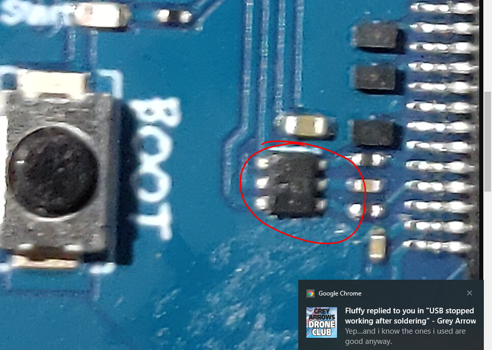
Here ya go, wondering if I shouldn’t have used those pads (even though it’s what their wiring diagram says to do)
What are you powering from it?
Just the USB but it wont connect when under lipo power either
Ah sorry, I meant from the 5v pad
receiver
Ok. What rx? Any of the 5 pin regs blown underneath or getting hot?
So i just realised the JST for the VTX is directly under these pads, could it be that i have doubled up on them and just need to use some others? Crossfire Micro. getting hot when plugged in? nope nothing warm on the board…when i plug in the lipo all the usual noises and lights occur RX boots up and binds as well just wont connect to the PC anymore
Have you tried another usb cable? Stupid I know but worth a try
Yep…and i know the ones i used are good anyway.
Nah thats just flux from my flux pen being massive lol
Not sure if there is a cap big enough for that to happen on the usb 5v line.
Not sure then. If it wont connect via usb even with new cables or a pc reboot with nothing attached to the fc, something has popped
everything lights up though, makes no sense if its fried.
I don’t know what soldering iron you’re using but sometimes with a mains powered iron you get a voltage on the tip… depends on the isolation someone said to me once.
If the circuit is susceptible to voltage it can harm things.
I use a gas powered iron for those situations… They heat up very quickly too!
Hope I’m wrong and it is just a dry joint.
out of interest i found this article clip from: http://www.farnell.com/datasheets/86958.pdf
Most soldering irons should be hard grounded (i.e. <5 ohms) and
ESDS should be grounded before coming into contact with the tips.
This hard ground is needed because the vast majority of soldering
irons have some form of temperature control, either by switching
the iron on or off at limits, or by using high frequency effect. These
control mechanisms can produce electric fields and thus require a
low impedance path to ground to prevent high potentials from
being accumulated which can damage ESDS (ESD sensitive
items).” (EN 61340-5-2 Section 5.2.10)
1 Like
Pretty sure the stm chips have built in diode protection for this or something on their inputs. Its been a lot of years since uni!
Might be a daft question but have you changed the settings in beta flight to reflect the changes you have made?
Also if you have both vtx and Rx using the same 5v and other pads then you may need to move one to a spare uart.
I’ve just soldered a buzzer on to my nazgul board but made sure I used an unused uart
Yeah I think its because ive soldered it onto the UART the VTX is using, just strange that it would cause it to not connect via usb. I cant really change anything in betaflight as my pc simply doesnt recognise it when i plug it in now.
I might be totally wrong. I just assumed that each uart was to be used independently