All newbie here - Ive bought a “broken” drone to fix up - only a sailfly x. Camera didn’t work (thought why buy a broken one and learn by fixing )
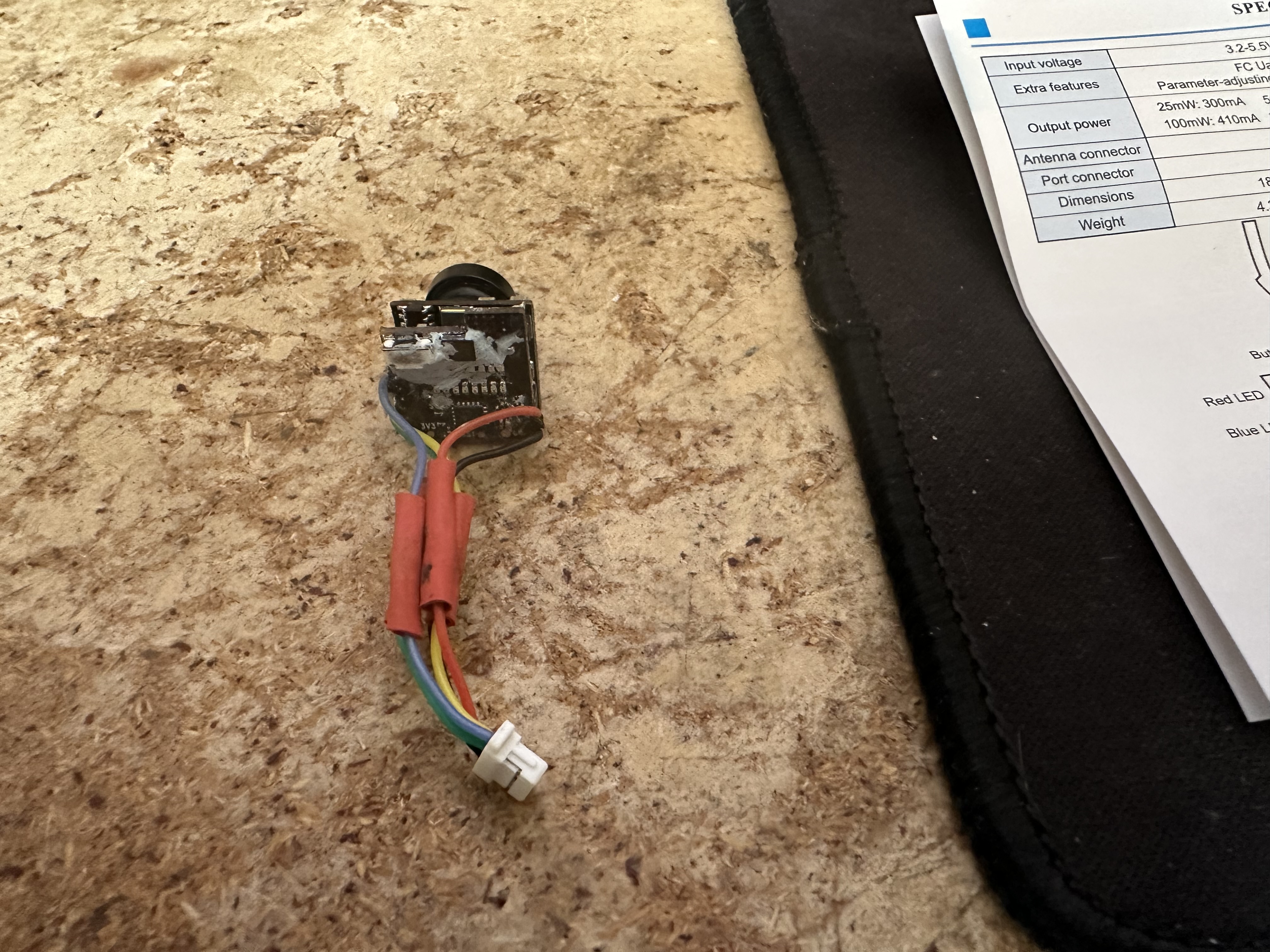
See the pics attached of the broken cam with no antenna.
Now see the other cameras, how do I go about putting the wires into the plug on the broken camera to fit onto the FC…. Electronics is all new to me - ask me about adjusting sights in wind for shooting and that’s my space
This - is all new. Thanks for any direction and guidance
Hi, Joshua Bardwell has a video on how to replace the JST connectors (balance plug) on a LIPO battery. I believe it is the same process with the micro JST connectors on your camera. You can also solder the wires straight to the FC but that is quite tricky what with the tiny connection points.
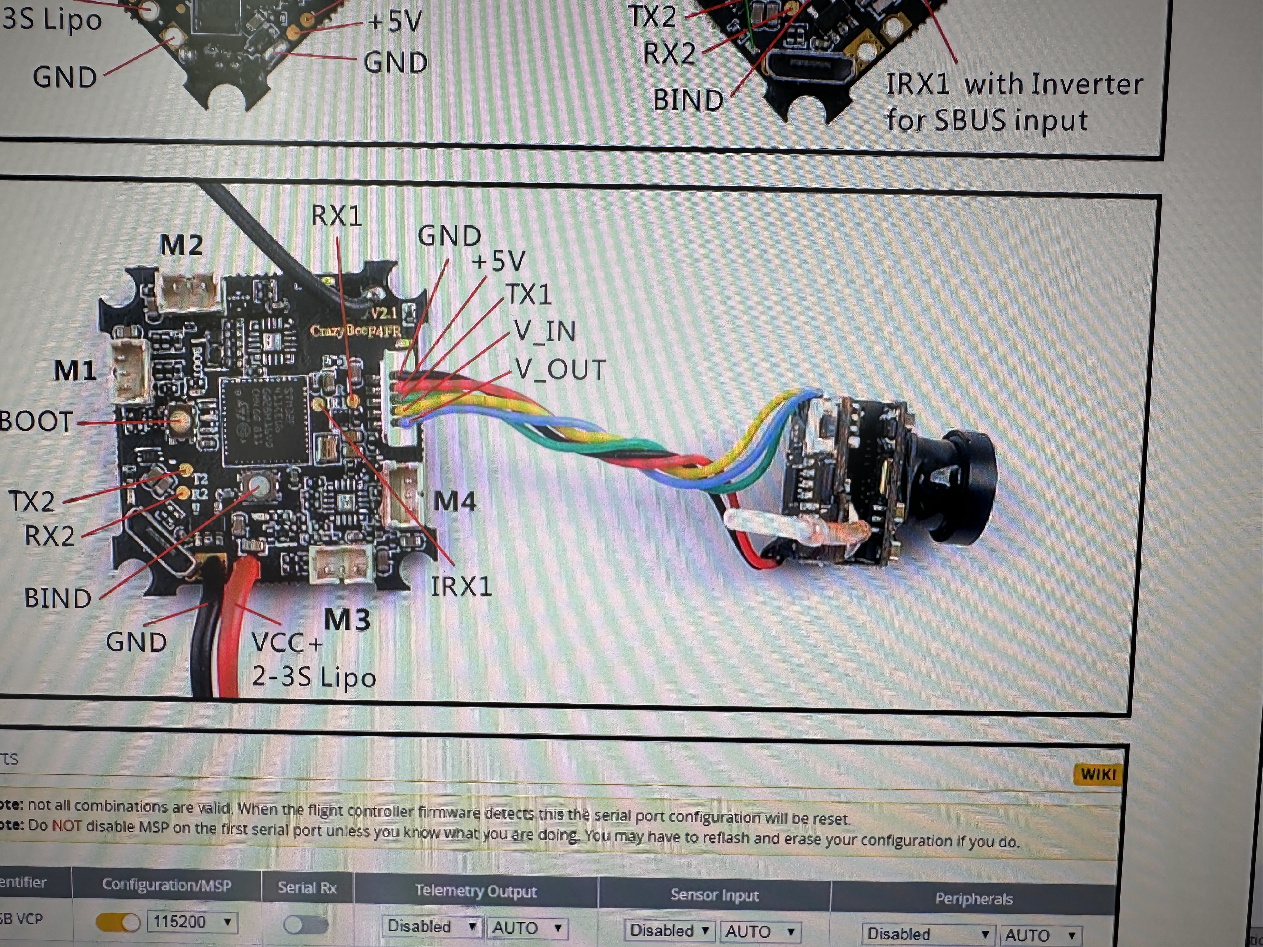
Based on the image at the top it should basically go :
> wires from new cam to broken cam plug
---------------------------------------------
- black from left and right   =>   GROUND
- red from right              =>   POWER
- red from left               =>   TX PIN
- yellow from left            =>   VIDEO IN
- green from left             =>   VIDEO OUT
But your cam says it wants 3.3v (edit: 3.7 actually), and your pin is gonna put out 5v.
Correction
I wrote the rest thinking the cam wanted the 3.3 volts a lot of fc’s have a pin for, but it’s actually 3.7v. It does make the rest of the post a lot less clear, but it might still be useful as it is what I would try.
The premise would be the same but you would either check the level shifter can handle the voltage on the low side, or just output slightly less than 3.7 from the step down converter. Those amazon boards will be rated for 3.6v in on the low side and I’m not sure you would have an issue in practice.
Old suggestion, continued..
Your cam says it wants 3.3v, and your pin is gonna put out 5v. I don’t see a 3v3 pin doing a search for the controller, so you might want to use a bidirectional level shifter like:
That way you shouldn’t damage the camera by sending 5 volts over the data lines, nor have communication issues from the cam side pulling its data lines up to less than 5, which you may if only use a step down converter placed between power/ground pins.
If use a logic level converter you would put flight controller power into the high voltage (HV) pin, cam side power into the low voltage (LV) pin.
Ground(s) to their respective GRD pins.
The data pins in any of the other opposing gates on their respective sides.