I’m looking to construct a basic 25x25mm pdb. I’ve seen some random tutorials on YT on how to create a basic one by using a prototyping board. Does anyone know the best place to get those prototyping boards from, or should I just get a cheapo board from ebay. This isn’t going to do anything complicated like provide a bec. It’s just going to provide power to 4x single esc and v+/gnd to the FC.
What is the maximum current you are expecting to pull ?
1 Like
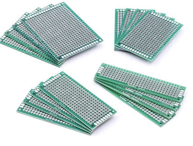
If you’re just using protoboard then yeah go for ebay or aliexpress if you don’t mind the delay. You’ll want ones with a 2.54mm pitch for most things.
If you want to dive in and make something clean for the long-term I use easyEDA who are partnered with JLPCB, a large PCB factory. You can draw PCB’s without placing components just by making the board directly, then send the gerber file off to be printed for about £6 for 5 copies. You’ll be waiting 2-3 weeks for the results to arrive but they’re great quality and look super professional.
Bloody years since i used to build things on Vero Board. Happy days!
I build my own flight controller using these
Don’t know why my links are not working
Might need through hole copper
Probably around 90A overall.
4x 20A ESC and whatever the FC/Cam/Video/RX needs, so probably a couple of amps.
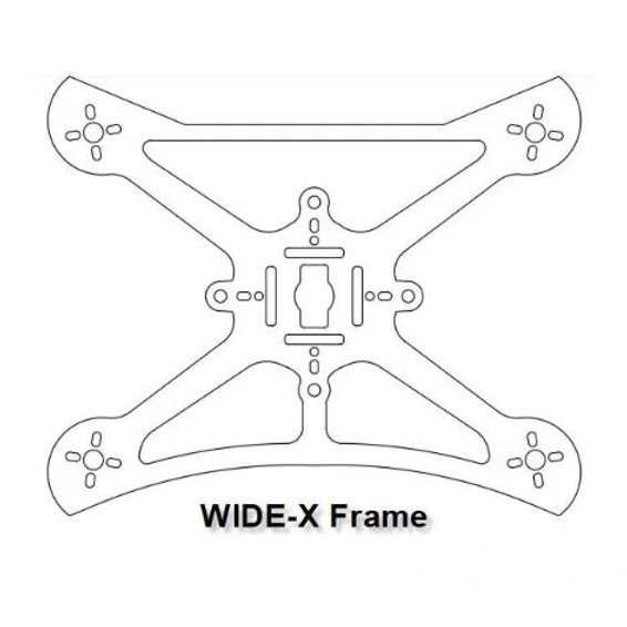
My problem is finding a PDB in a whoop format, ie, 25x25. Matek make one that is near to that size, but still bigger. I want it to fit on a Twig 3" frame, which offers 25x25, but wouldn’t take a 30x30 (nor would I want to use one as the overhang would offer a route for getting damaged.
So after researching I looked up how to make a basic pdb on Youtube and up popped a video. it’s I suspect an overly simplistic view of how to do it, but I will run a separate bec if I need one.

You’re going to need at least a 4 layer, multilayer board, 2oz. copper, plated through holes, designed by somebody with experience of heat dissipation.
Don’t even consider ‘vero’ style perforated board, It will never handle the current.
IMHO buy one, it will be cheaper and more reliable in the long run. ![]()
I used to have electronics design software, I’ll have a look for it as it might be still in an old laptop stashed away somewhere.
If I remember, I think it was called “Live wire”. I used it for visualising current flow in circuits such a Kirchhoff Law and the like….too long ago.
Hopefully I can remember how to convert a circuit to PCB, I think it did it automatically. Give the dimensions and we can play with it if I”ve still got it…![]()
For my RPi projects I usually buy boards from:
I used to haunt their store here in Corby and Kettering on Saturdays, I though they died a death after closing down in the high streets……![]()
1 Like
That’s the problem. So far I can’t find anything in 20x20 or 25x25. If I was building something on a standard frame, this wouldn’t be an issue. But my pcb area is a max of 25x25 in a diamond configuration.
This pdb is about the closest I’ve come to finding something commercial, but unless I can come up with a workable mounting system I will probably lose one of the mounting holes on the frame. i would rather have the pdb under the FC, but if I went down this road, maybe that’s a compromise I would need to take.
Another possibility I considered was to run some strips of copper around a sheet of PE in the form factor that I need, solder directly to the copper. Thickness wise, maybe the stuff they use on roofs to hold slates up, which is about 2-3mm as I remember. Would be heavier than a PCB, but should take more amps.
Are there any types of connectors like Wago that could be used? This doesn’t necessarily need to be a PCB, it just needs to breakout a power cable 4 ways and be able to handle the amps.
I still have an old electronics design program somewhere, I think it was called Electronics Workbench, from uni days, but it was more of a design and test your circuits type program that ran from dos.
@PingSpike Thanks for the Tandy link, I also thought they’d gone the way of Maplin, long ago.
For one of my early quads, many years ago, I made a wiring harness that handle the power distribution, neat, cheap, fitted well as its size was optimised.
Could be an option for you?
Do you have frame height to use an adaptor mount to suit your frame and a bought PDB?
I found the PCB software, but it’s failing to create the circuit, it’s also won’t generate a circuit smaller than 35mm and no way of orienting the circuit the way you want it.
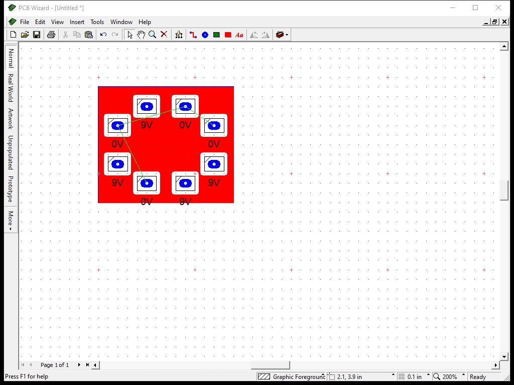
Sorry…
Yes, the wiring harness might end up being the best way. Maybe using bullet connectors instead of soldering the esc wires to it, or possibly xt30 connectors. It would make it more modular and easier to swap esc’s (should I ever need to). I did wonder if it would be possible to create a build with the possibility of changing the esc/motors if needed without massive amounts of hassle, which this would achieve. From measuring everything, the frame will take the Chaos 20A and 25A without issue. Anyway, getting ahead of myself. ![]()
Technically frame height isn’t all that relevant. I could use an adaptor mount. In fact I would prefer to mount the boards in a square config as opposed to diamond, as it would make life simpler.
I ordered one of those Matek PDB’s regardless of whether it will work or not. I will find a use for it on something else if it won’t work on this build.
I guess it’s also possible this is too much of a folly.
Anyway, thanks for the help and suggestions.