Vifly Buzzer help

After last weekends treasure hunt, I wanted to fit my ViFly finder 2 to my TurboBee 160.

After watching videos and reading the instructions I note that the output suggested in the instructions are already being used on what seems to be a very small board.

Can I use any alternative contacts or should I solder to the ones already in use but suggested by the instructions?

Only spare contacts

That looks like a nano VTX in a mount board isn’t the flight controller under it? Its probably an all in one ESC and flight controller?

Just done some research for you mate heres the wiring guide for your flight controller:

SucceX-Micro-Flytower-1000x1000

Bottom left corner you want the BZ- pad 5v and GND :+1:t2:

1 Like

I connected mine to the buzzer 5v and ground connections

Yeah seen that. Something already connected to Bz pad. Looks like vtx at a guess

Got a photo of the flight controller?

I’ll have to strip it down. May be tomorrow now as capt smirnoff popped round for a bbq :laughing::poultry_leg::tropical_drink::tropical_drink:

Pictures coming at lunch.

I will say that the B is currently taken as is every other possible contact on that board. So do I solder two wires to the Bz contact or remove what’s there and solder to the bz and other available ground and 5v on the top board?

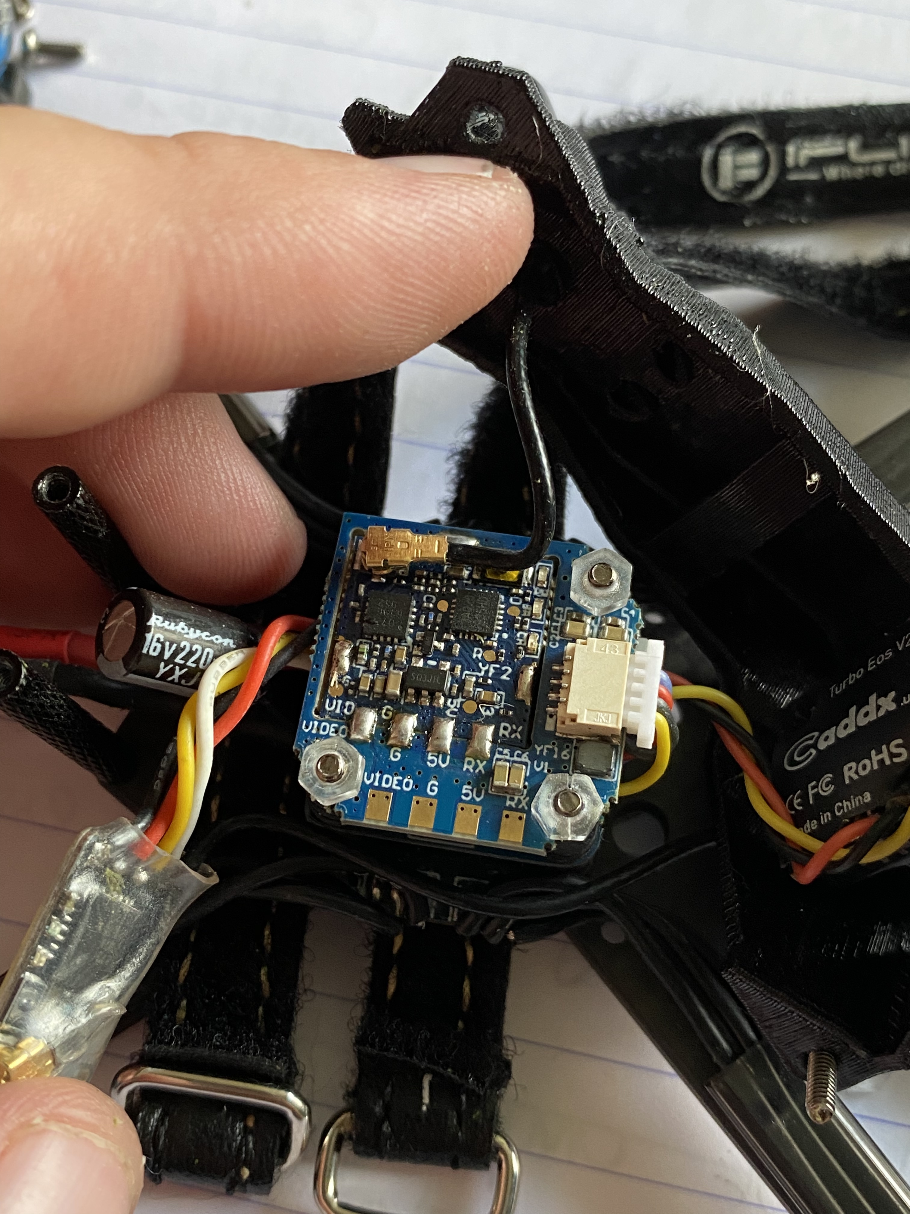
Without seeing the board its impossible to say. If something is already attached to the BZ pad then I’d guess they’ve re mapped the resource to a different function.

my mistake got the zoom goggles out and the bz is clear. ( the board is tiny!)

I’m assuming taking a 5v and g from the available contacts on the vtx will be ok?

Depends if its 5v out or not most VTXs have a 5v out for powering a camera directly from the VTX that will work fine. You’ll need to find the wiring guide for the VTX though to make sure or test it with a multimeter :+1:t2:

Done and works well. Thanks again for your help @DeanoG60

2 Likes

No problems, any time :ok_hand:t2:


Not the prettiest but it’s in there and working

Ah up mate like to catch up with you regarding the above as I’m having the same issues

1 Like

Nick, Your best bet it soldering to the three legged transistor next to the buzzer - pad. Trust me. The transistor leg that’s on its own.

1 Like

Anytime mate. From memory it was a just a 5v or ground that I needed so any would do.

Not sure that’s the same for b+

I’ll have a look later they are tiny though :pleading_face:

1 Like

I used a magnifying glass on mine.
It helped to pre tin the wire and pad then just needed touching to create a bond

Well a big thanks mate as I did what you said and it worked treat, it took 1 pair of glasses and a very strong magnifying glass…

image

Just one more Q is super glue safe to use on my board as the transistor is lifting on the side iv soldered. Hence I was going to fix it in place with some glue …

2 Likes