Quick question, just been tinkering with my Firefly as had a bit of a bump last weekend. On opening it up Iv discovered 2 of the wires have come off the ground and the Sbus thing is I cant find where its come from ?. Looking at the diagram it seems a little confusing as what goes to were
I thought you had to have both ground wires soldered to the FC ??, can anyone sched any light on this ???.
As long as every module has a link to ground somehow it doesn’t really matter how they get there.
Ground is sometimes called the “ground plane”, or “common ground”. It’s all the same thing…
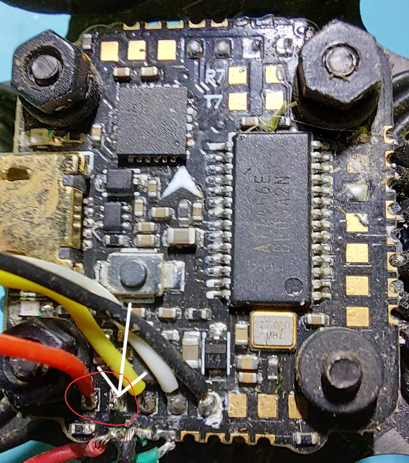
As for Sbus I think it should go between the two connections I’ve marked in red… Assuming it’s using the DJI Controller. Otherwise it depends on the RX module chosen.
Cheers mate looking at my FC and the 1 above as the chip is in a different orientation
The arrow shows were the ground came off, so looking at the order the wires are in the pad next to the black should be the SBus but there is no solder on there to indicate it came from there…
If no manual, then perhaps go with this one. What does it say is Serial in in Betaflight? If it is on UART 4 then it makes sense that SBUS goes on where you think the ground goes.
Which then leaves you wondering where ground goes, but that’s lucky… any ground location. Assuming of course that the wire really is ground and has not been given the wrong colour.
I hope it goes without saying that you’ll be using a smoke-stopper once you power up after rewiring?
well iv dobbed the SBus wire next to the the live as in pic below, but the strange thing is, it depicts you only attach 1 ground to the FC ??. Iv soldered the another ground wire to a spare G pad which seems ok. But on firing it all up I have VTX and it connects to my hand control but nothing works i.e switches.
Iv had a quick look on BF and everything seems ok so not sure where to go from here
So, you’re using the DJI controller as your remote, right?
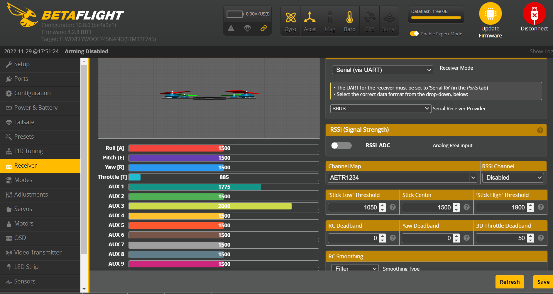
In Betaflight you have:
Ports tab:
Serial Rx set for UART4 (and no other UART)? (since you are attached to the RX4 pin)
Receiver Tab:
Receiver Mode: Serial (via UART)
Serial Receiver Provider: SBUS
That’s all that should have been set. If it’s not working, you could try changing the Serial Rx port config to see if any if you’re actually attached to a different port.
Otherwise you may have a continuity problem. So, check your wiring with a multimeter.
You have an F7 FC so you don’t need to use a dedicated SBUS port on the FC. You could try wiring to a different RX pin on another unused UART.
I hope Im wrong but there is a chance that when the sbus wire broke off it touched the VCC pad next to it. If thats the case it would have blown the potection diode for sbus
As @Yith had already said you should also check continuity of your Sbus wire from Vista to FC as it might just be a damaged wire causing an open circuit
Fuck me Nick, £170 Fluke Meter for drones? Lol That definitely doesn’t have a diode setting unfortunately. Have you tested continuity of your Sbus wire from Vista to FC yet? Also you can try wiring the Sbus to a different Uart as Richard suggested also just to rule out an issue with the Uart on the FC
Iv tested the wire between the 2 pads
Test between the Sbus and ground on the Vista the the diode should be ok
I could change it to RX5 on the side of the board see if that makes a difference…
You can actually view the signals being sent along the sbus wire using a logic analyser.
I bought one ages ago when I was having problems with a FC not supplying a signal to an ESC. It turned out the signal wasn’t getting off the microcontroller to the ribbon cable.