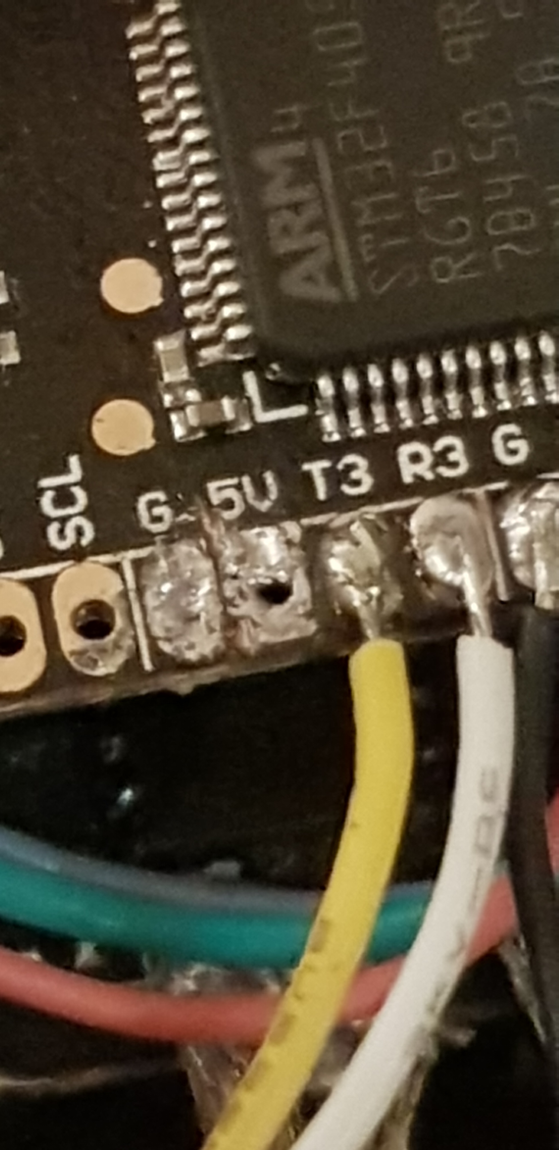
What are the reasons why I’m not getting power to the 5v pads on my FC? A short? Continuity tester across the pads doesn’t bleep a short but reads 280… (280 whats in not sure) but is that enough to cause the problem? There’s some crappy soldering that could be the issue…
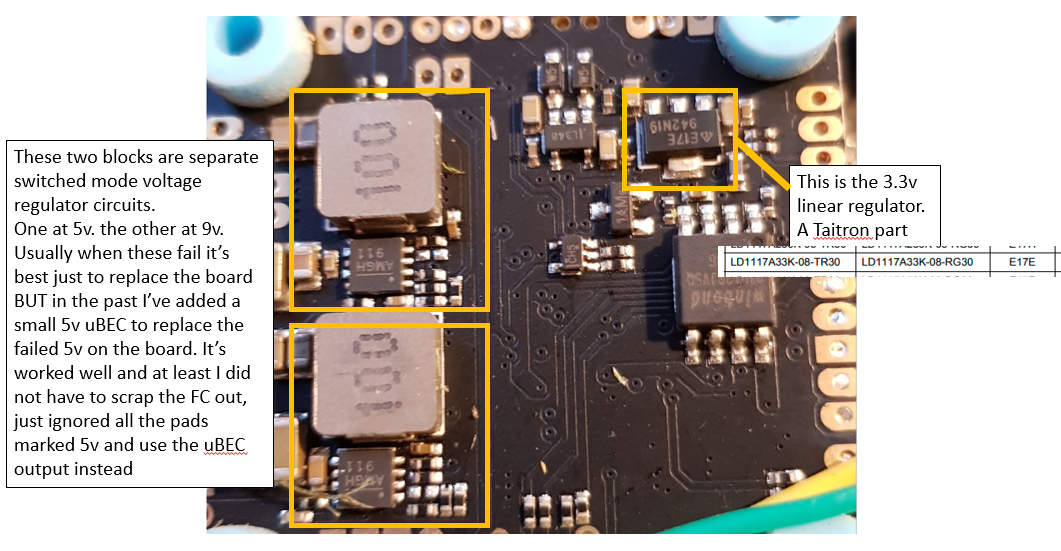
Could be a blown regulator. It’ll be a small black chip with 5 legs. If it’s blown, it’ll have a bubble on the top and/or gets hot seconds after the fc is powered up.
Probably looks like this

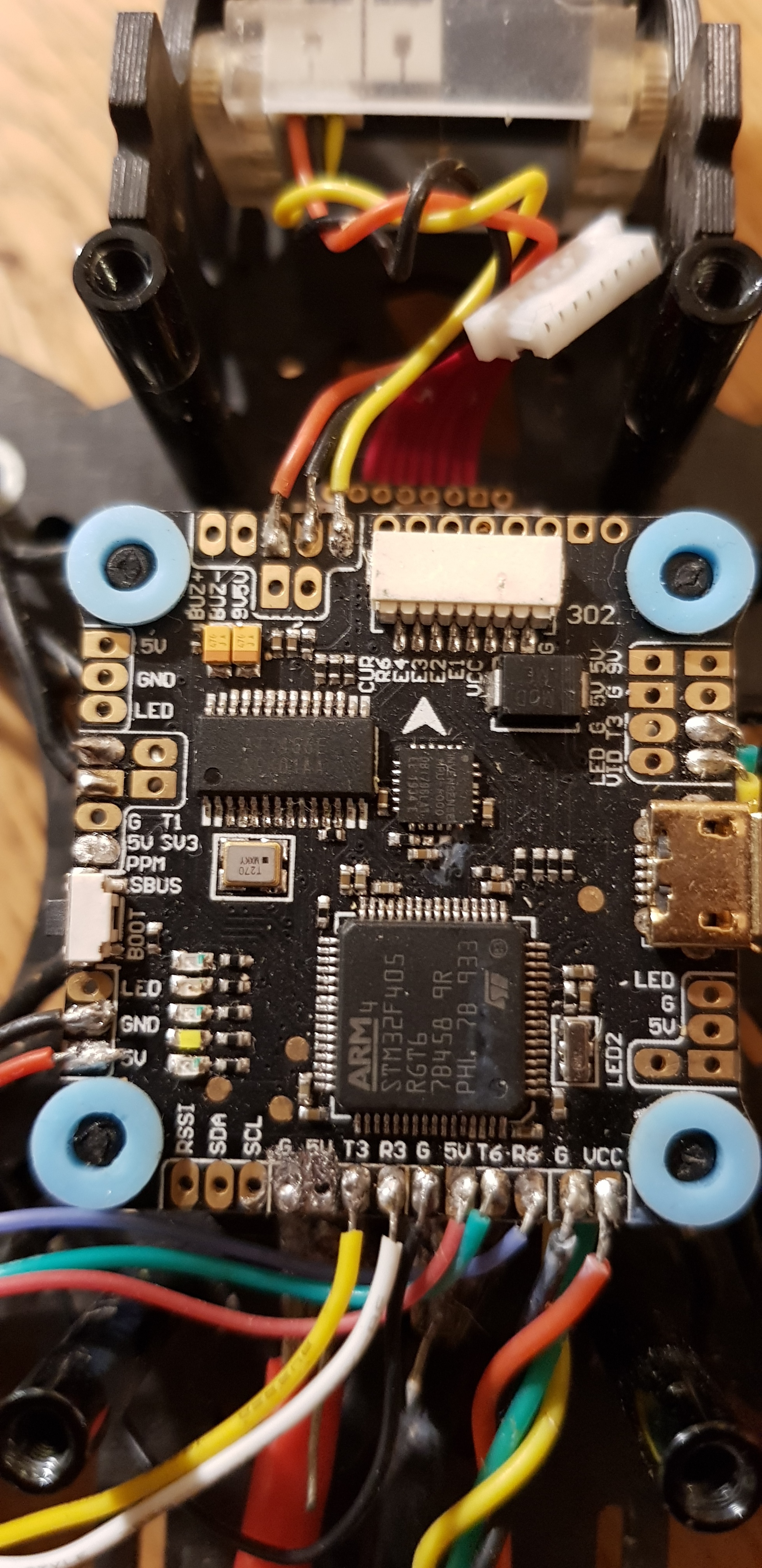
I’ll be underneath…
send us a pic
Cheers
Steve 
1 Like

I’m only sayin, but there’s holes in the pads. Pop the wires through then solder. Then snip off underneath. Makes it clean and less chance of a short
1 Like
Ahh! There you go. And as for crappy soldering…the reason for all the gunk was because this new solder I got turned into plasticine when melted! It was awful stuff, but id gunked up the board before realising it wasn’t necessarily me… Thanks for the tip with the holes tho… Always wondered what they were for!
1 Like
Don’t worry mate. I’ve been soldering since I was a teenager a long time ago, and I’m well shit!
2 Likes
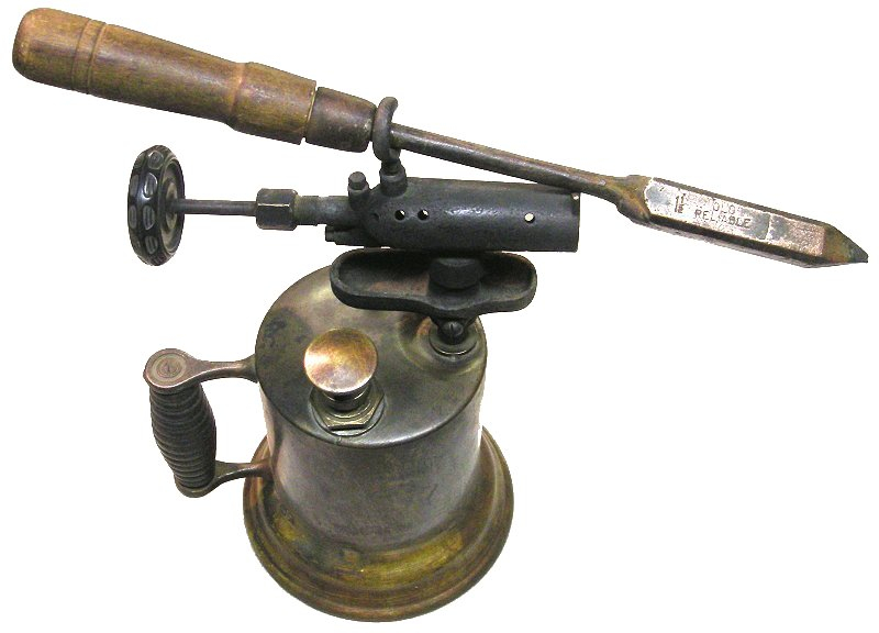
AHHHHH. DON’T USE LEAD FREE SOLDER!!!![]()
![]()
![]()
![]()
Use a 60/40 Lead/Tin with a Rosin Core. With lead free you always have to use a significantly hotter iron, and because unleaded solder has a low specific heat capacity (ability to retain heat) it turns to “plasticine” when the iron is removed, and quite often fails to anneal to the pads but instead crystallises creating a high resistance connection.
Whenever I’ve acquired any piece of DIY electronic gear the first thing I do is open it up and check the soldering. If the builder has used lead free solder it gets removed and I rebuild the kit with proper leaded solder. To do this with a quad is quite a quick job but, and any radio hams will know, I once acquired an Elecraft K2 HF transceiver that didn’t work. These are expensive boutique radio kits, the kit is more expensive than many pre-built radios of similar spec. Anyway the previous owner had used lead free solder, and possibly used a rusty nail heated on the gas hob to melt the stuff. I ended up removing every single component (probably close to a thousand when the optional modules needed the same treatment), removed all the crappy solder, and rebuilt the radio. This could be called a labour of love, in my case it was an example of shear insanity. Once rebuilt and the various stages realigned it is now a supreme performer, easily comparable to prebuilt flagship models.
Because of regulations concerning pollution, especially as electronics usually end up in landfill, lead free solder is solely used in industry but the way it is applied is a world away from the needs of the hobbyist.
Here is a video demonstrating the industrial process.

Even with this type of industrial process I believe the manufacturer still factors in a significant failure rate due to boards being ineffectively soldered.
Nidge.
1 Like
I agree with @Nidge and @notveryprettyboy, I would also add that using a quality flux is a must, making sure everything is clean and pre-tinned. A good Iron with a decent tip as well.
1 Like
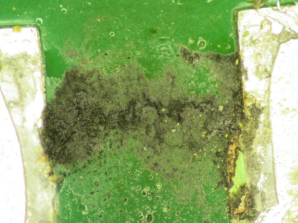
On of the most common causes of intermittent faults are dendrites forming between track on the surface of PCBs. they can form under components and under conformal coating. The are related to contamination, voltage, humidity and the design seperation distance on PCBs or components see images under cleaning section Bob Willis Photo Album Downloads for Training & Social Media - Bob Willis
New board…? £36…
Done… So don’t tell me the was another way now!
Note to self, don’t try to help @tom.at.rye in the future !
1 Like
Sorry Stevie, but adding a new UBEC is beyond my skills and patience… I gotta fly again man! I gotta fly again…
Your help and expertise are as ever sincerely appreciated!
1 Like
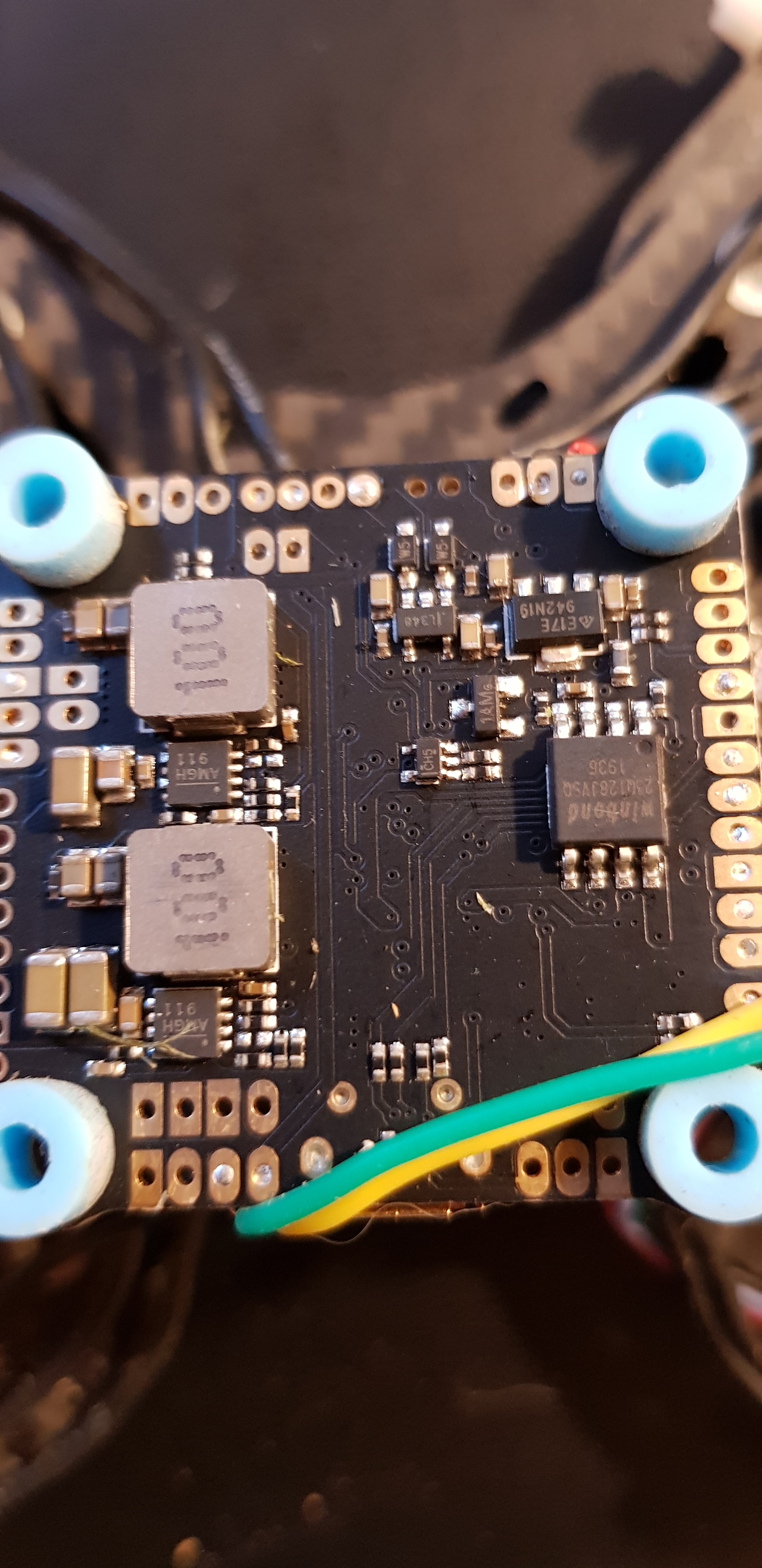
Just interested Steve. Why would they use switch mode regulators on an fc? Seems overkill.
@notveryprettyboy
Reduces the heat Mate, if they used a linear 5v regulator pulling 2A from a 6S pack it would have a power loss of:-
((4.2*6)-5)*2=40.4 watts
That’s a lot of heat to get rid of on a fully populated PCB with no spare copper mass to utilise as a heat sink.
That FC has 5v & 9v reg outputs so it could be twice as much.
1 Like
Sooo… What… Could… Be… Wrong… Now…?
Very simple task, wiring up a crossfire nano to the FC.
Binding, check
Green light on nano and transmitter, check
RX/TX wire crossover between nano and board check
Not a blip showing in the receiver panel of BetaFlight when I wiggle the stocks and flick switches!
I’ve tried two different ports and I’ve tried reversing the tx/rx wires so what is like to knew is, an I missing something Really Stupid?..
Help!
Config tab? Serial & crsf?