Some Direction

Iv rebuilt the Apex update the FC (F4 NOXE V3 Flight Controller 5V 10V BEC OSD(Lite/Full Version() which is running off my t-motor ESC (MINI F45A 6S 4IN1_ESC_FPV_T-MOTOR Store-Official Store for T-motor drone motor,ESC,Propeller) .

Had to swop the pins round as different config to previous FC but did double check them. When I plugged into BF I dont get the second tone and cant power the motors up, am I right that the second tone it the ESC talking to the FC ?? if so I can only think theirs an issue with the wiring… :man_shrugging:t3: :man_facepalming:t3:

1 Like

Yes the second set of beeps is the FC and ESC shaking hands. Almost certainly going to be the wiring from the ESC to the FC if youve had to change the wiring. Have you got any photos of the FC and ESC connections Nick?

Hmmm no I haven’t Steve but a trip to the garage will resolve that, I know the pins were a pain in the ars to do son im thinking one might be bent or just not making…

I bob out there now and have a gander :+1:t3: :cold_face:

Theres a good chance that youre spot on with this. Check theyre all fully inserted. Sometimes when you push them back in they dont lock in fully and push out the back of the connector as you plug it in

They seem ok but a nightmare to sort as you can see :exploding_head:


Your plug in the fc may not be wired correctly. Eg the power wires

image

Wiring definitely wrong if the diagrams you pointed to in the first post are correct


Yah there my FC and ESC, where have I gone wrong :grimacing:

The power and ground are 100% wrong. On both diagrams the power is on the far side of the plug but on your wiring its around the middle of the FC.


As for the grey wires you will need to look at the diagrams and put them into the correct slot on the plug

My 1st 2 are right VCC and Ground

I have power to the FC

Hold on Nick, have you just used the grey wires for the power and ground? That makes everything way more complicated lol

:grimacing: I have but I do think there all in the right place :+1:t3:

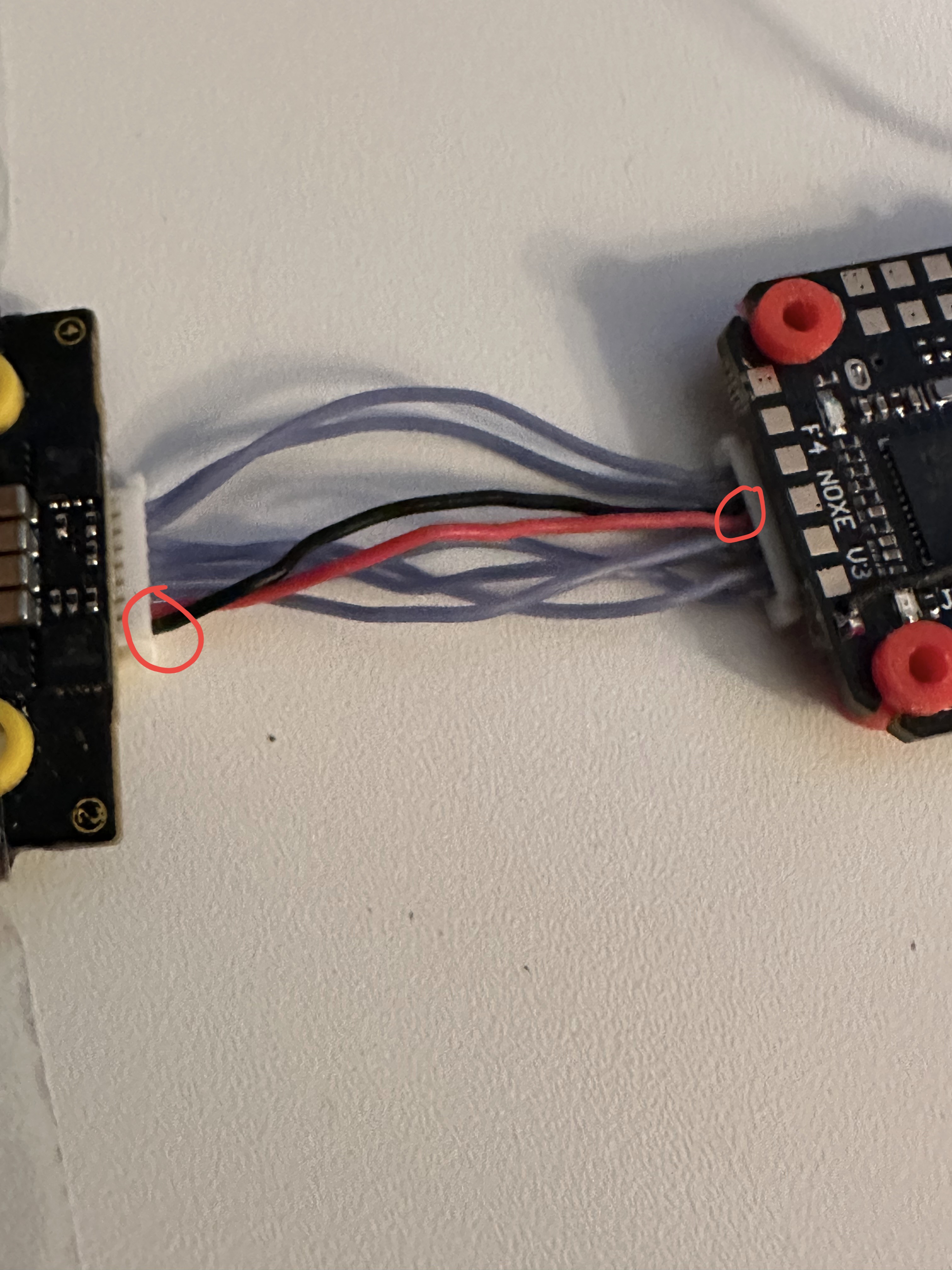
Looking at the diagrams and tracing your wiring it does look like they are correct but you were pulling them out of the plug anyway so why not use the correct colours when putting them back? :man_facepalming:t3::laughing:

1 Like

I only did the FC side that’s why the ESC side is right

So if wirings right not sure whats going on, is it possible to solder to the board ??

Right your next step would be to leave them connected together and with a multimeter check continuity from the pins on the back of the connector socket. That way you are checking the wires and the connections in the plug at the same time

Is the motor protocol set on betaflight?

Neither side is right because you have grey wires for the power and ground on both sides :rofl:

Like that idea :+1:t3:

Defernatly makes life more interesting :rofl: :rofl: :rofl: