Hey Nick
I’ve got tubes like this, what’s the exact size of yours? I can send you some

1 Like
Cheers Steve there about 70mm long and not 100% on the OD but will check later 
3 to 3.5mm OD mate, and please let me know how much I O U 
Hi Nick
Sorry for delay, hectic time
Mine are 3mm OD and 100mm long
Got 10 of them
Also got some pieces 300mm long but they have a slight bend
Let me know what you need and I’ll stick in post tomorrow
Hey Steve no worries I’ll happily take the bent one’s, just cut them into 70mm lengths if you don’t mind and they be great, thanks. Let me know how much I O U
In post tomorrow Nick
Mates rates 
Love this! Those are my colours all day. 
Thank you Steve, I’ll bring the biscuits next time we meet up
1 Like
Hey, happy holidays!
I have not been missing, did just bite off more than could quickly chew with a project, and not had much to show.
I saw that betaflight had added initial support for the RP2350’s (Raspberry pico 2) and I love those chips so had to play with it.
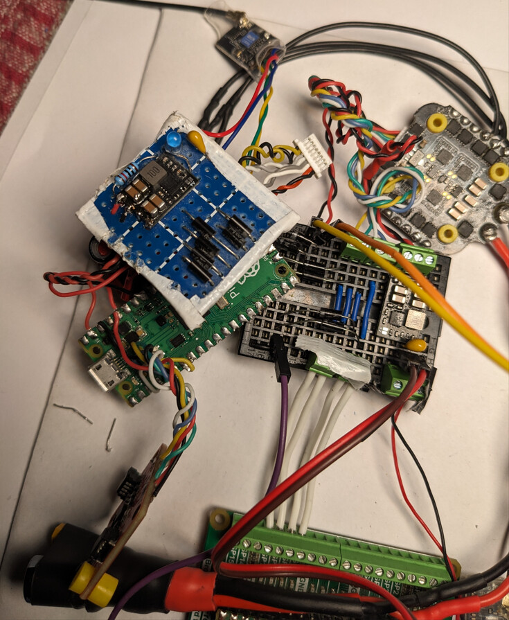
I only had these TDK ICM20948 gyros which betaflight didn’t have a driver for, and I didn’t want to stop working on the project before my 42688P chips arrived from abroad (est. at 2 weeks).
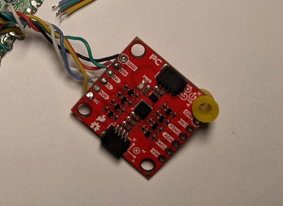
So I decided to write a quick driver for it  and you know what they say.. you don’t do it because it’s easy, you do it because you think it will be easy and then are too stubborn to stop and do something more productive with your time.
Did get the driver working in the end, and submitted a PR with a request for comment.
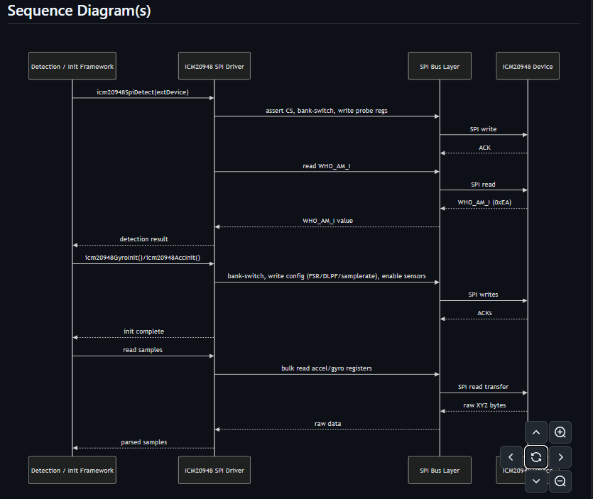
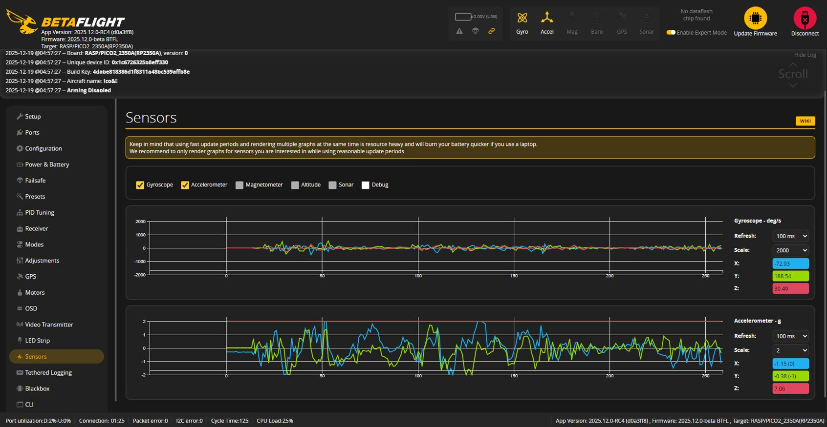
I’m doubtful they will want to clutter the code base with support for older modules but it did allow me to make use of their wonderful bot that does a little audit of the commit and catches a lot of potential issues.
If not merged to core (which would be understandable), I’ll leave the patch history on github for anyone that might find themselves here on a search in future, and you can know the implementation has at least passed the integration tests.
DEVICES DETECTED: SPI=1, I2C=0 (0 errors)
GYRO: (1) ICM20948 enabled locked
ACC: ICM20948
GPS: NOT ENABLED
OSD: NONE
SD-CARD: Not configured

BUILD KEY: 4dabe818386d1f8311a48bc539affb8e (2025.12.0-beta)

System Uptime: 232 seconds, Current Time: 2025-12-19T05:04:50.485+00:00
CPU:26%, cycle time: 125, GYRO rate: 8000, RX rate: 250, System rate: 9
Voltage: 0.00V (0S battery - INIT)
Arming disable flags: THROTTLE BOOTGRACE CLI MSP ARM_SWITCH

# tasks
Task list             rate/hz  max/us  avg/us maxload avgload  total/ms   late    run reqd/us
00 - (         SYSTEM)     10       1       0    0.0%    0.0%         0      0   2333       0
01 - (         SYSTEM)    994      15       0    1.4%    0.0%        25     48 232910       0
02 - (           GYRO)   8000      35      12   28.0%    9.6%     11586      0 1865285       0
03 - (         FILTER)   8000      25       2   20.0%    1.6%      3760      0 1865285       0
04 - (            PID)   8000      46      17   36.8%   13.6%     30567      0 1865285       0
05 - (            ACC)   1000      30      12    3.0%    1.2%      2945    194 232856      21
06 - (       ATTITUDE)    100      20       5    0.2%    0.0%       115     17  23315       6
07 - (             RX)    241      28      10    0.6%    0.2%      1735     87 171648       7
08 - (         SERIAL)    100   52110       1  521.1%    0.0%       482      0  22693      17
09 - (       DISPATCH)   1000      15       0    1.5%    0.0%        36     59 232920       1
11 - (BATTERY_CURRENT)     50       1       0    0.0%    0.0%         2      2  11659       0
12 - ( BATTERY_ALERTS)      5       7       1    0.0%    0.0%         0      2   1167       0
16 - (      TELEMETRY)    500      31       0    1.5%    0.0%       159     91 114676       0
17 - (       LEDSTRIP)     60       0       0    0.0%    0.0%         4     20  13862       0
22 - (SPEED_NEGOTIATION)    100      13       0    0.1%    0.0%         6     48  22691       0
RX Check Function                  13       1                        82
Total (excluding SERIAL)                                26.2%
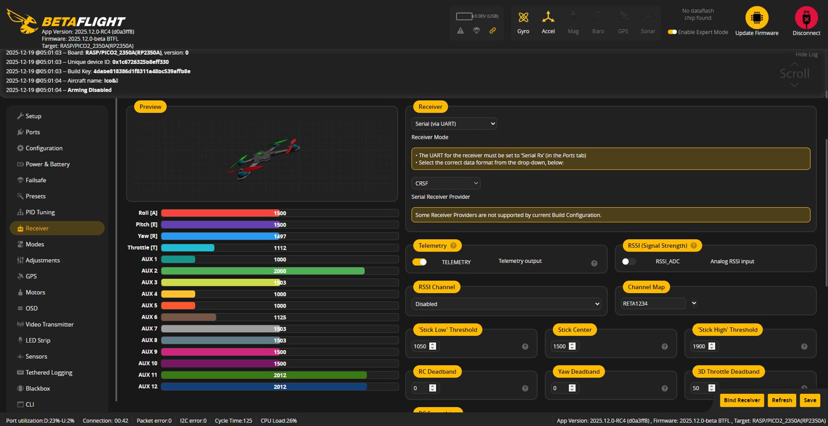
Once a gyro was connected, the other peripherals were happy to co operate, so I got the receiver hooked up to one of the uart ports and left the other for the digital video transmitter.
For ESC connection it’s a little more interesting (at least for me), as I’m pretty familiar with bi-directional logic level shifters but had no experience with voltage clamps which is what was need here.
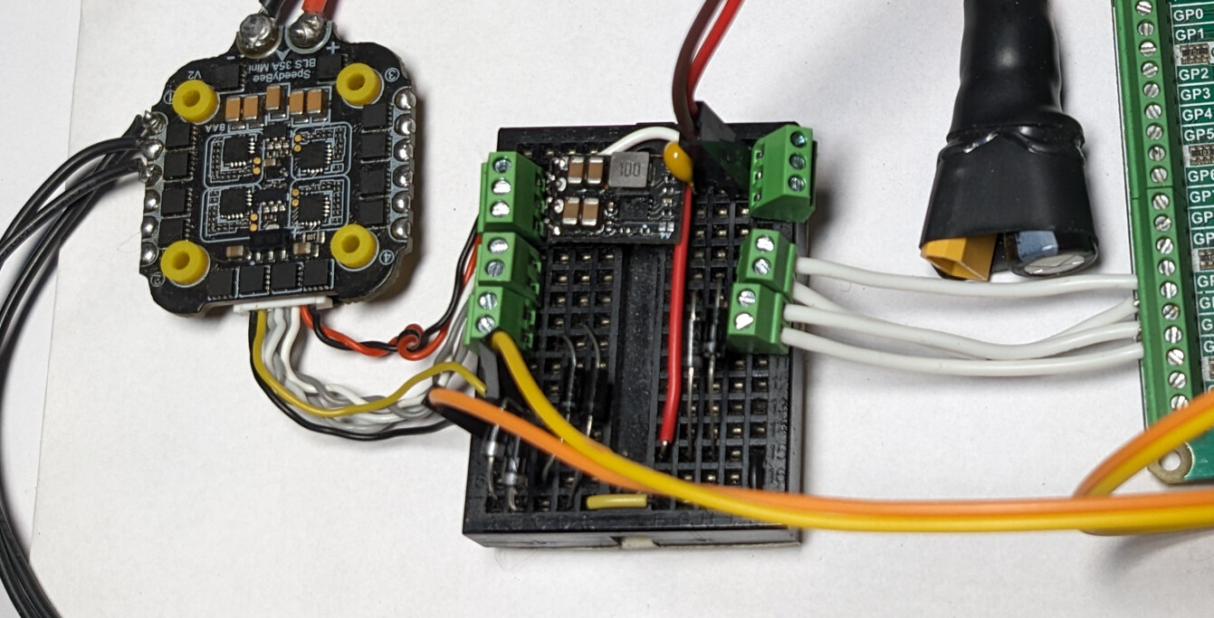
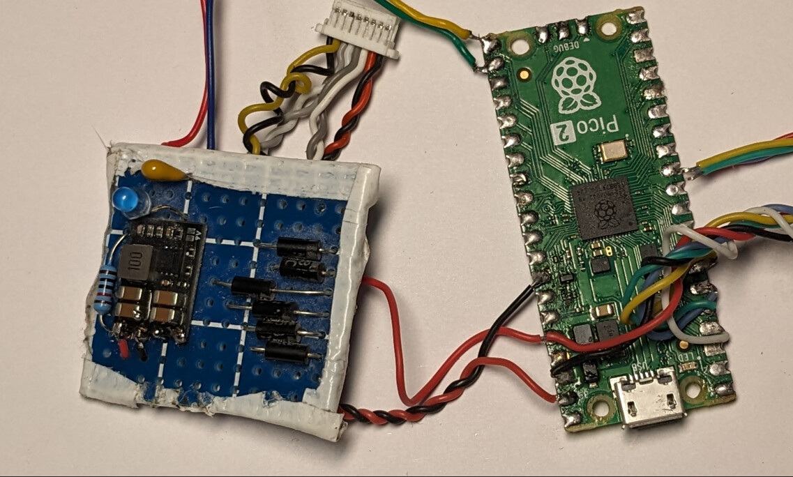
Because ESCs can produce these huge inductive voltage spikes that instantly fry the 3.3v pins on the pico (yes I did) I had to add some circuitry, but for the high speed DShot protocol, standard level shifters are gonna be too slow and introduce propagation delays or signal distortion, so we need to use a diode clamping circuit instead.
I went with 1N5817 Schottky diodes for fast switch speeds and low forward voltage, then by tying the anodes to the signal lines and the cathodes to the 3.3v power rail, any voltage that exceeds the rail gets shunted away from the pin, protecting the hardware without that capacitive load that would otherwise degrade the high speed signal.
Super interesting and great to have another tool in the box.
Here’s one I blew up earlier, melting a hole through the chip while releasing a plume of smoke.

I was hesitant to plug in the battery as I didn’t want to lose another pico, but thankfully the clamp did its job and now we have bench tested all the core communication protocols: SPI (Gyro), UART (Receiver) and DShot (ESC); so to add more of the same like an SD card slot on the remaining hardware SPI, should be trivial.
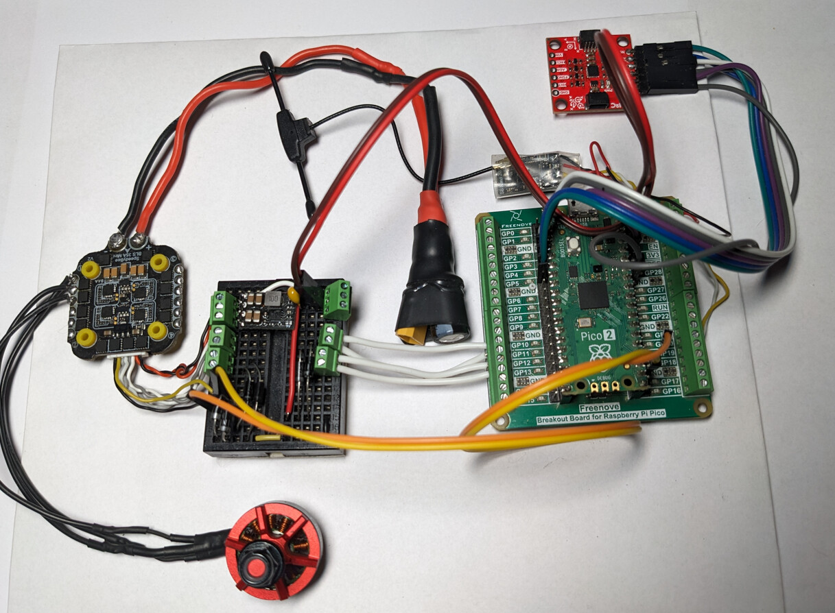
Am playing around with a smaller harness to see if can mount something to a whoop pusher, or a Volodor 3.5. I have some smaller individual esc’s arriving tomorrow and while try to mount the whoop set up.
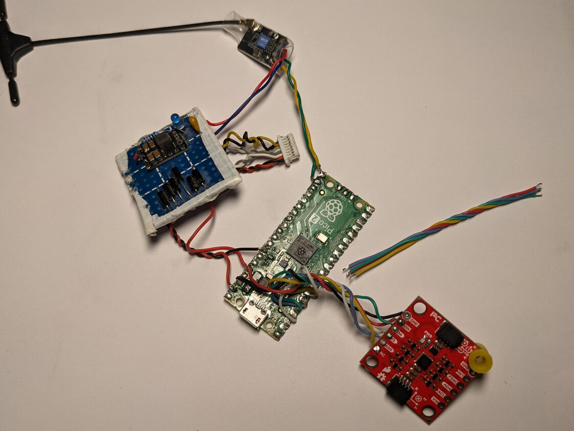
Reality is the pico form factor is not ideal for the frames that are out here, at the size I’m interested in. So I think next I’d like to try design a pcb and make a custom flight controller.
I have the more modern ICM chips here now and will be using those, a pair of ICM42688Ps (is what my HDZero Halo build uses), and some surface mount 42605’s, both of which have drivers in betaflight already
It’s been a great learning experience and one that I hadn’t felt so encouraged to take with the ST-Series chips, as had very little experience with them and no dedicated dev set up for it.
Where as this was a really approachable and a fun introduction to flight controller design, so I appreciate team adding the target.
As always thanks for reading.
6 Likes
does the diodes get warm ? would it be possible to opto couplers ?
1 Like
Hey happy holidays, yes a little.
So optocouplers is using infra red transmitters and receivers to pass light as the signal?
It looks like a really elegant solution, though I think might be a bit like the bi-directional logic level shifters, in that if you are be able to get them fast enough for DShot, it won’t be cheaply or simply. Unless I’m mistaken.
I definitely will explore the method if not for use here then elsewhere, so thank you for the suggestion!
opto couplers are not expensive and can switch at some very high frequencies
Oh interesting, are there any you would try in this case or just thinking more broadly about what might be possible? It’s definitely interesting conceptually.
I’m thinking they look great for signal isolation, but that the high forwarded voltage drop might even lead to more heat.
For cost I think we are talking pennies vs pounds so maybe not totally insignificant.
On the surface looks designed for different purpose but do always love to play with ideas so will mess around with them. Cheers.
no idea as to what one to try without looking at various data sheets but you can also get some solid state bi directional isolators in a dil chip layout . been a few years since i played with them
1 Like

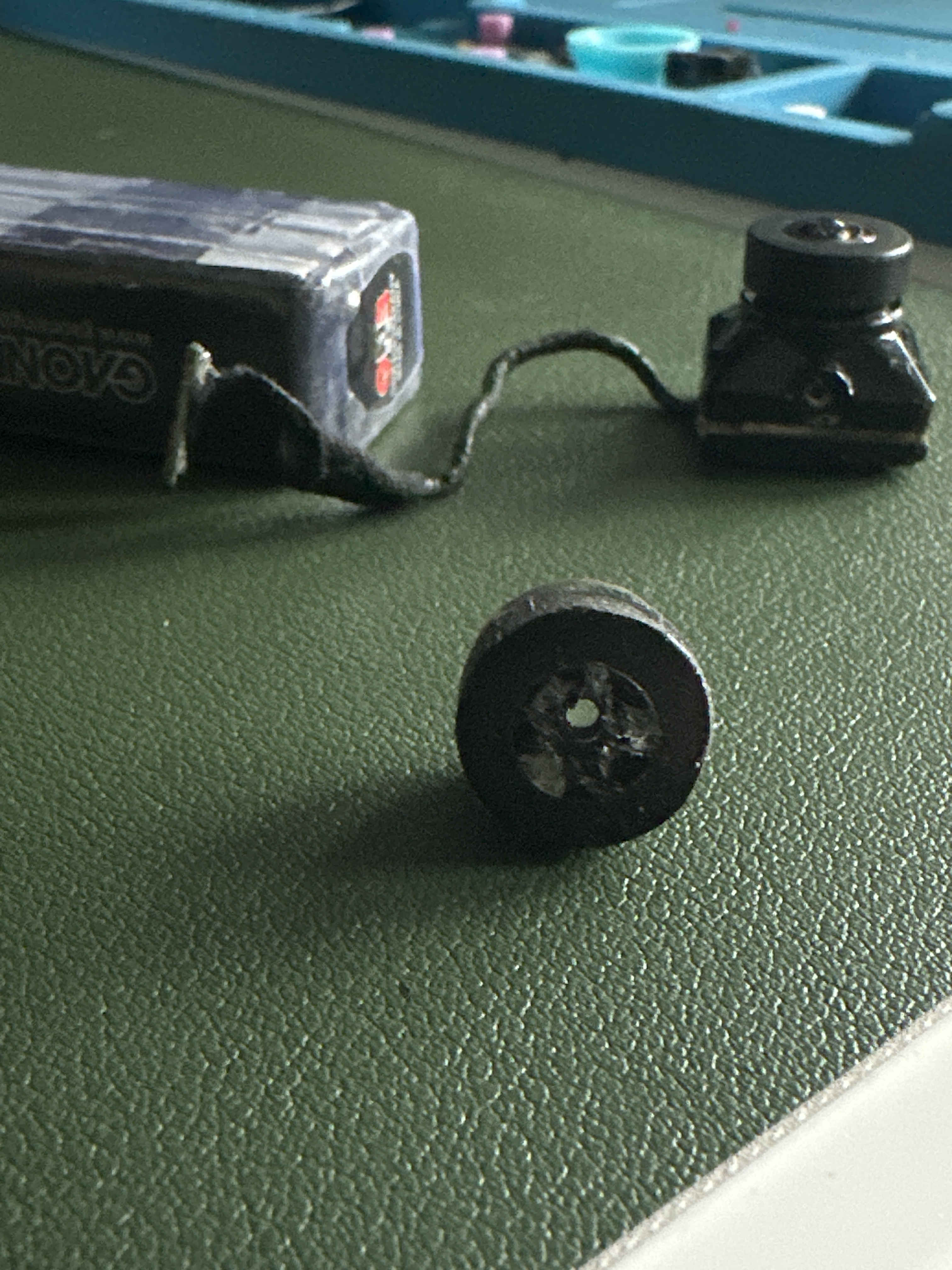
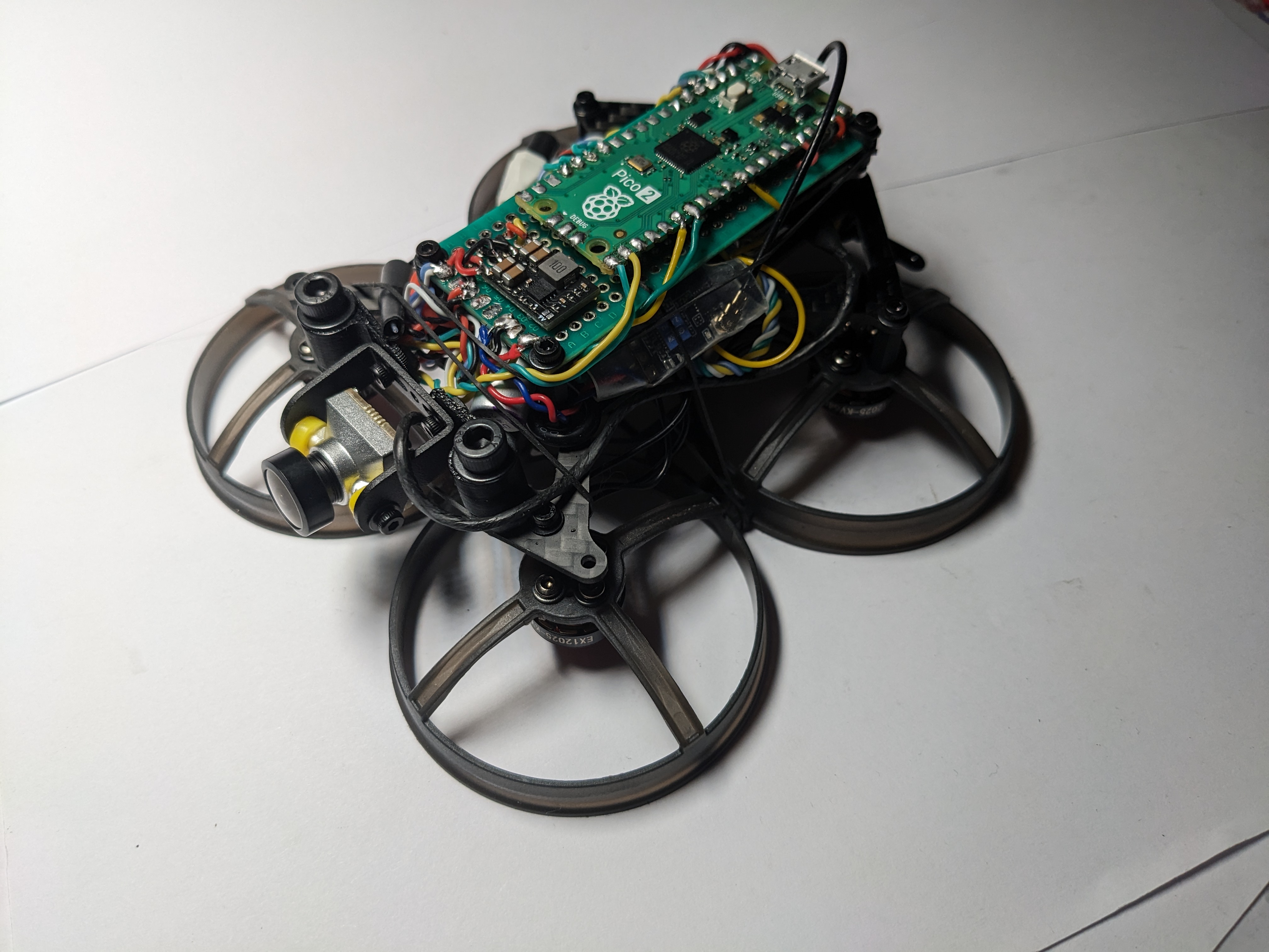
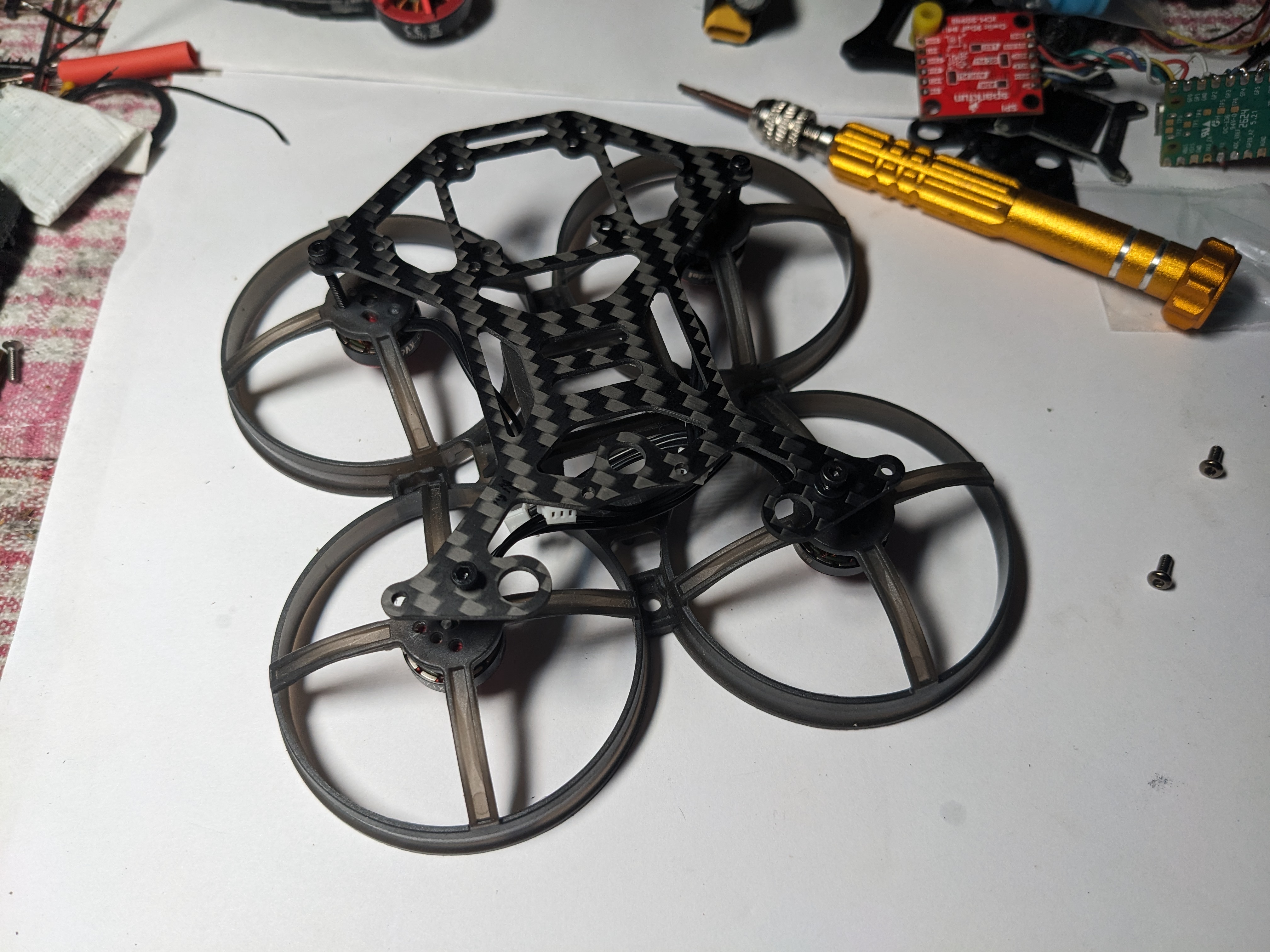
Hey guys! The pico build is coming together quite well.
I took a base plate from the BetaFPV 85 pusher conversion kit and mounted it to an upside down Happymodel Mobula 8 frame:
Gives a good amount of space for some 7x3 protoboard where we can mount the pico, step down converter and voltage clamp.
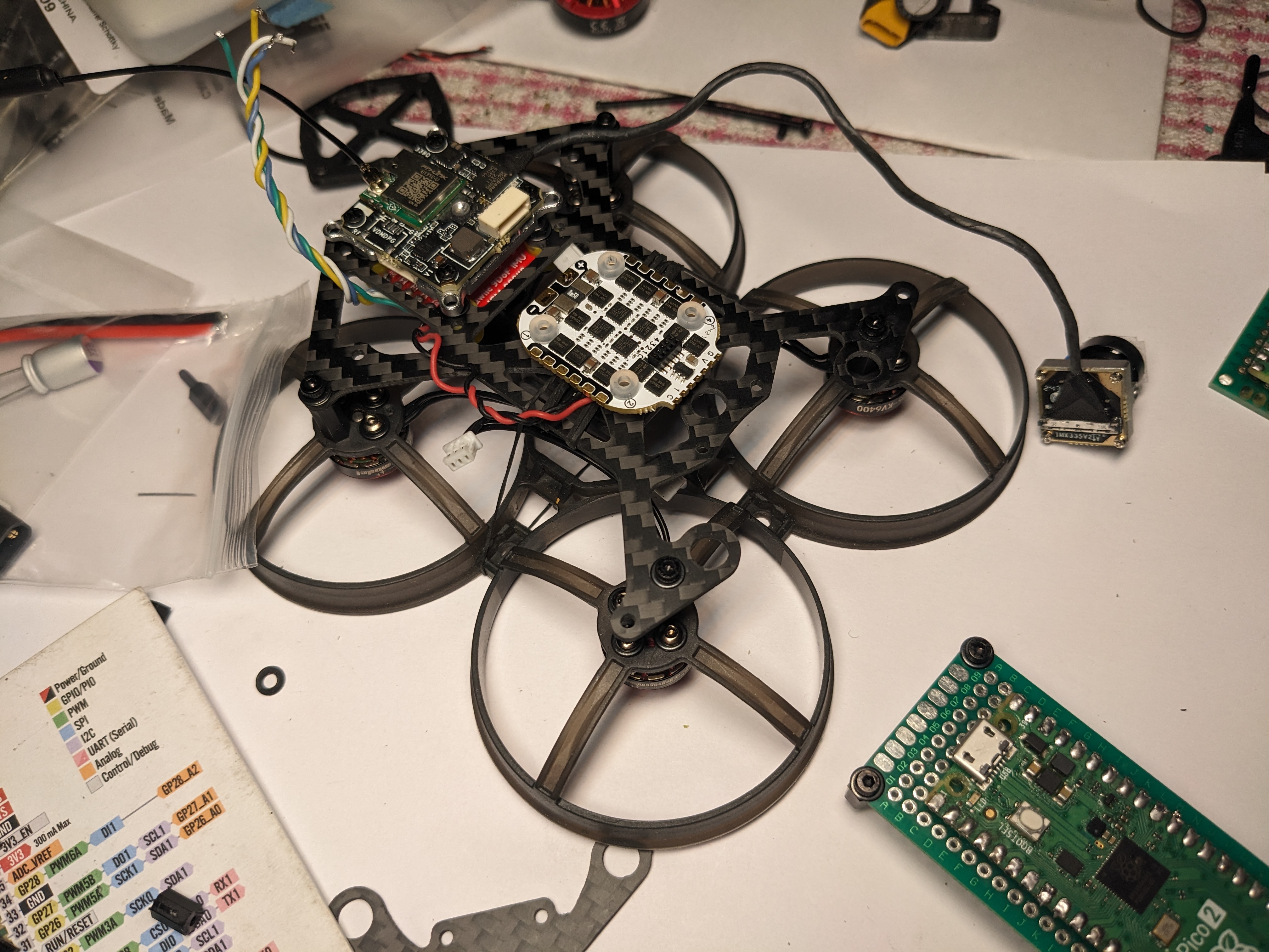
I mounted the gyro to the underside of the base plate, and the OpenIPC Thinker Tiny to the top side. Then went with the micro sized 16x16 Flywoo ESC and some 1202.5 6400kv motors from the Crux 3.
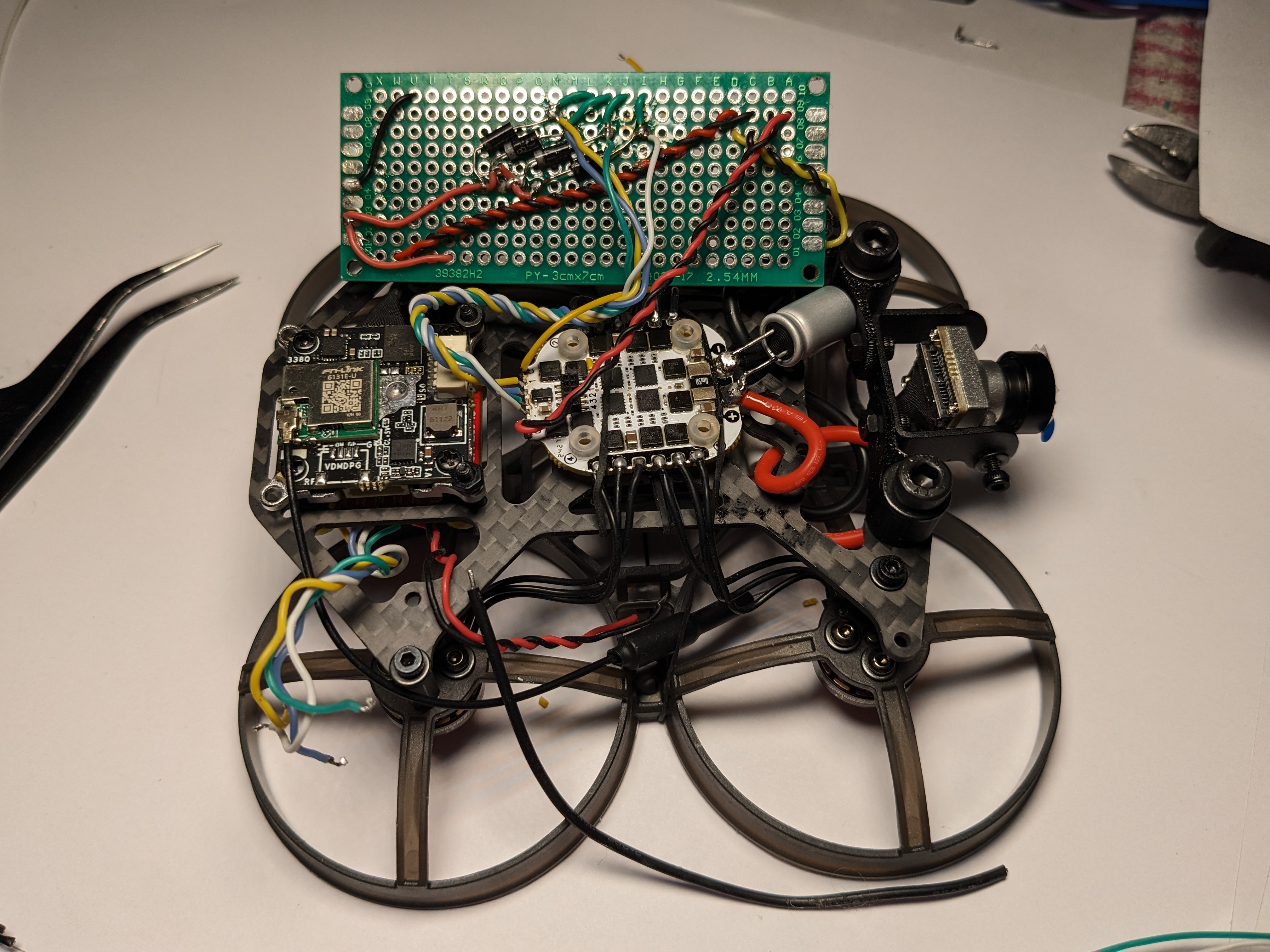
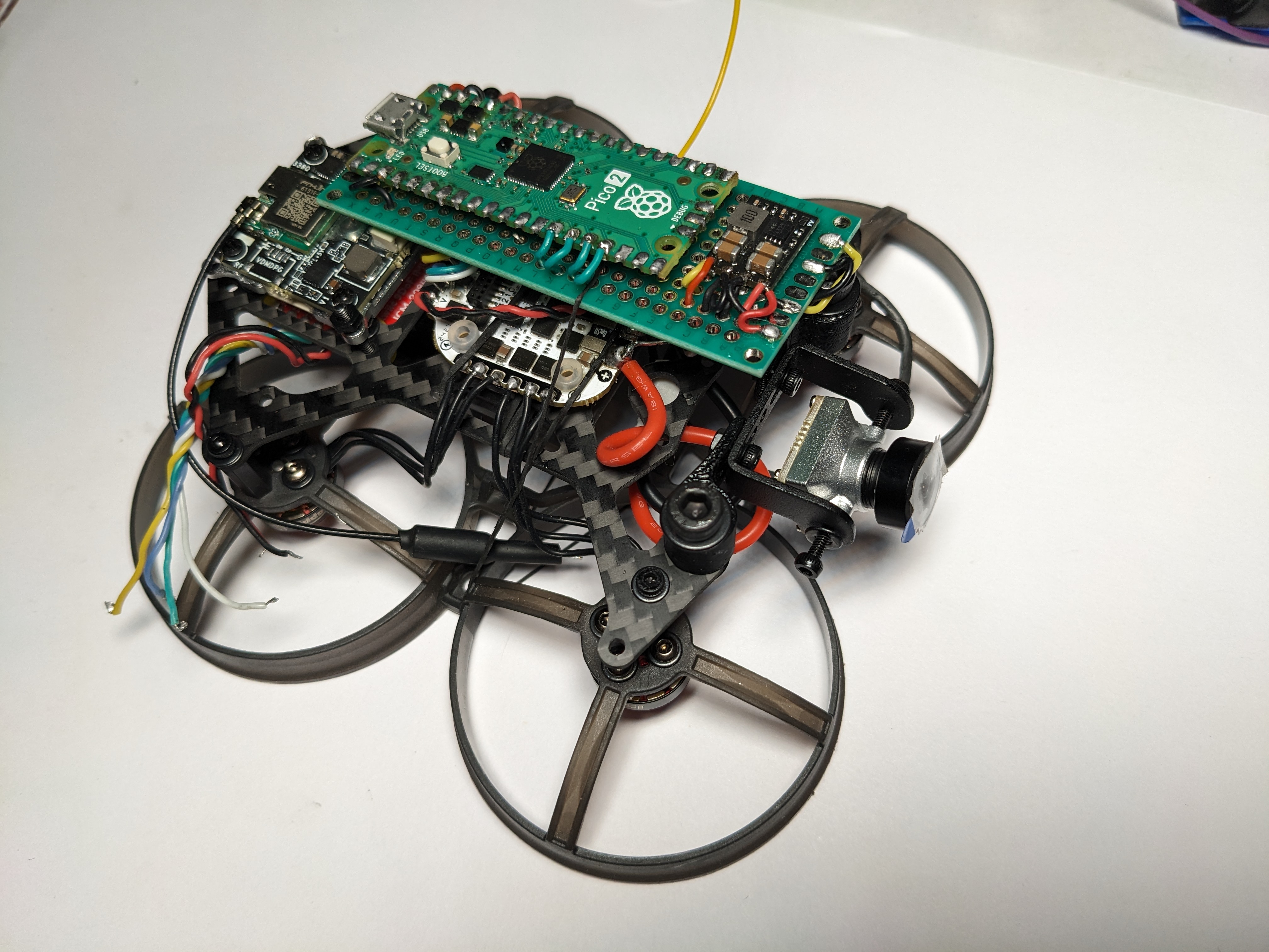
I don’t have the picture though assure you I covered the exposed leads on the underside with that see through brown tape you get in the lipo’s, before clamping down the top plate.
Repurposed the 3d printed camera mounts that come with the Grinderino and used them to create a mount for a mini to micro adapter I had lying around.
Did plan on 3d printing something but didn’t want to spend the time to come up with a good design, when I haven’t even finished the hardware side.
I think this came out alright and gives inspiration for something more permanent later.

Almost everything works on first go, but I do have an issue with the motors.
I think the signal wires are too long as dshot 600 is desyncing at around 50% throttle, and betaflight have not implemented 150/300 for this target yet.
So current task is to clean the signal lines through shortening the wires and improving the ground connection by wrapping each signal in its own dedicated ground wire.
We are very close to first flight!
7 Likes

3 Likes
Spent the last 90 minutes fitting the new Fkywoo O4 Wide Lens Set to the BetaFPV Meteor O4 Pro.

This is not the one that fits over the current O4 lens (which suffers with lens glare and black vignetting around the edge of the footage)
This is the new one, where you have to remove the original O4 lens and then fit the Flywoo replacement.
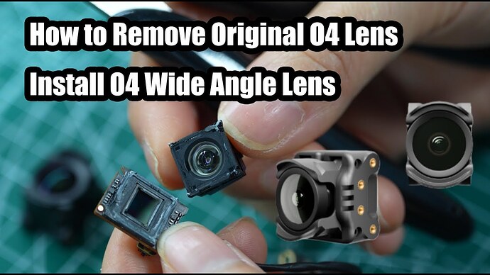
To be truthful, it was easier the I expected, the longest part of the process, was focusing the lens.
4 Likes
I’ve just installed a O4 wide lens on one of my quads’ O4 - nice!
I do get a bit more glare, I think. Anyone else has this feeling? I could be wrong.
the glare was mentioned as an issue of the ‘v1’ version (cap on top of the existing lens) - but was announced as resolved for the new v2 (the one in the video ^). Which one do you have? (not powered mine yet  )
)