Was just curious as i am on goggles 2 and vista and didn’t WTFOS to get my OSD.
Not sure mate as I’ve WTFOS all of my vista ?
You don’t need WTFOS with the goggles 2 only v1 and V2?
Out on the wing in the space designed for it.
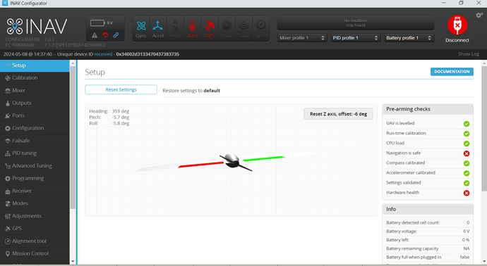
Ok a im all built but have a couple of issues not sure if anyone can understand the below. Have tried to google a couple of the lines from it but couldnt make head nor tail of them…
Entering CLI Mode, type ‘exit’ to return, or ‘help’
status
INAV/SPEEDYBEEF405WING 7.1.0 Mar 27 2024 / 14:34:15 (59a6ee61)
GCC-10.3.1 20210824 (release)
System Uptime: 726 seconds
Current Time: 2041-06-28T01:04:00.000+00:00
Voltage: 0.00V (0S battery - NOT PRESENT)
CPU Clock=168MHz, GYRO=ICM42605, ACC=ICM42605
STM32 system clocks:
SYSCLK = 168 MHz
HCLK = 168 MHz
PCLK1 = 42 MHz
PCLK2 = 84 MHz
Sensor status: GYRO=OK, ACC=OK, MAG=NONE, BARO=UNAVAILABLE, RANGEFINDER=NONE, OPFLOW=NONE, GPS=UNAVAILABLE
SD card: Manufacturer 0x3, 31154688kB, 11/2023, v8.0, ‘SN32G’
Filesystem: Ready
Stack size: 6144, Stack address: 0x10010000, Heap available: 1828
I2C Errors: 55, config size: 10467, max available config: 131072
ADC channel usage:
BATTERY : configured = ADC 1, used = ADC 1
RSSI : configured = ADC 4, used = none
CURRENT : configured = ADC 2, used = ADC 2
AIRSPEED : configured = ADC 3, used = none
System load: 6, cycle time: 1018, PID rate: 982, RX rate: 9, System rate: 9
Arming disabled flags: NAV HWFAIL RX CLI
OSD: MSP DisplayPort [30 x 16]
VTX: not detected
GPS: HW Version: Unknown Proto: 0.00 Baud: 115200
GNSS Capabilities:
GNSS Provider active/default
GPS 1/1
Max concurrent: 0
As you can see my GPS isnt talking to my FC and my Baro is not working, tried differant options in the baro but noting hence Im wondering if I have to fix my GPS.
May of found my problem found this little beauty floating around inside… not sure what it is but found where it belongs and soldered back… just how it’s the right way round ![]()
Seems to me that the wires in your GPS are incorrectly connected to the SDA, SCL pads which is why the BARO is screwed up and no gps signal
On the GPS
ONLY connect 5V GND TX RX and as I’m sure you know now TX on GPS goes to RX on flight controller and vice versa
Cheer Steve I’m thinking I may have bigger problems and god knows how it came loose ![]() could only happen to me
could only happen to me ![]()
Had a go at soldering it back on, if wasn’t for the rattling I’d of never known it had come off…
Just checked it and have 5v across it so im assuming its ok ?
Swopped them over still the same
SDA, SCL should NOT be connected show us exactly how it is connected
Are you talking about the brass pillar with the yellow rubber on it??
That is not soldered, it’s screwed
Bless no the brown ?? With the 2 soldered ends I’ll take the positives from that, you can’t tell I’ve soldered it back in ![]()
Bless…
You’ve got wires in the wrong holes
Ignore the two on the left (SDA, SCL) just connect the 4v5 to GPS 5V, GND to GND, TX3 to GPS RX, RX3 to GPS TX
Then check in ports that you have UART3 set to GPS at 115200
and depending which version of INAV you have ……
Check in configuration tab you have GPS enabled
Check in GPS tab you have it enabled and set for auto baud and auto configure
If you can’t sort it you had better bring it to heli field on Saturday
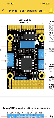
I’m really confused now as the picture below is of the soldier pads I.e the underside of the board and it look like the configuration is different??
I definitely have the red 5v and ground right
So the cables that are soldered to the GPS should be in the connector as labeled.
Note:
Transmit (T) goes to Recieve (Rx3) FC connector and Receive (R) goes to Transmit (Tx3) FC connector.
Ignore the SCL and SDA on the Flight Controller, you don’t have those pins on your GPS.
Once it’s done there should be two missing connections on the left hand side of the connecter (as you see it from above)
Ok I understand that but what puzzling is why they connect differently pleading whether you solder them or use the JST connector??
Thing is I don’t want to put power to the wrong pad and end up trashing it. Could check the pins with a mete just to make sure, would of thought they would be the same ![]()
purely because of the way the PCB designer has laid it out, there are physical restrictions on space and layers that he/she has to follow.
Don’t compare the two, just choose your method of connection, concentrate on that and ignore the other. Don’t overthink it, it’ll hurt the brain ![]()
Yep all up thanks think I spent a little to long on it yesterday ![]() I now have a healthy wing.
I now have a healthy wing.
Just need to sort controller now as works in Inav but not on its own I also have a constant beeping which I can turn off thank god…
Can I check I have the ESC in the right port as in pic below, it’s in S1 at the mo.
S1 Is correct for Motor/ESC ![]()


